|
If you're wondering if the installation of your engine kit is within your abilities, read on. Thousands of people with little or no prior experience working on Harleys have
successfully installed engine kits in these bikes. They're really a very simple engine to work on, and the pushrod valvetrain and air cooled design both simplify the disassembly and reassembly of
the top end. If you have the tools you'll need, and you can read and follow directions, are reasonably patient and careful, you can do this yourself and save a lot of money.
Many of the procedures below are also covered in
our tech tips videos, and the instructions below may or may not reference those videos. So be sure to also review our videos page if you'd like
a more in-depth look at a given procedure, chances are you'll find it there.
So let's get started. The following tutorial is oriented toward the XL engine, but 99% of it applies to Big Twins as well.
-
Gather the needed tools and supplies. Here's what you'll need:
- A Factory Service Manual. Don't scrimp on this, it's important. Get a genuine HD version, they're the best
- Common hand tools, including 1/4" and 3/8" drive socket sets (english), a hex key set (better known as allen wrenches), an assortment of screwdrivers and pliers.
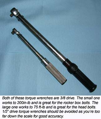
- A torque wrench that works for inch-lb ranges. You'll be torquing fasteners as light as 90in-lb. Generally speaking, either a 1/4" drive or a smaller 3/8" drive torque wrench is ideal.
- A torque wrench for torquing the head bolts, which are torqued in steps from 9ft-lb to 42ft-lb. We recommend a larger 3/8 drive torque wrench for this. You're operating
too far down the range if you use a 1/2" drive torque wrench. Pick up a 1/2" 12 point socket for this torque wrench, along with extensions of various lengths. A swivel adapter can be handy too.
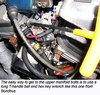
- A 5/16" T-handle hex key wrench (Allen) with a ball end and a long shank is a great tool for removing the upper manifold bolts. Bondhus offers a T-Handle set that's reasonably priced and works great.
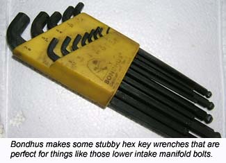
- A 5/16" L stubby type hex key wrench (Allen) will be needed to remove the lower manifold bolts. Many people cut down a standard L wrench. Bondhus makes a really nice set of stubby wrenches though.
- Shop towels (common blue shop paper towels available almost everywhere work well) and brake parts cleaner are good things to have handy.
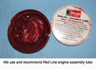
- Engine assembly lube. We recommend Red Line assembly lube and we have it available.
- A medium file and a set of feeler gauges for gapping your rings (not needed if you purchased the pre-assembled option from us).
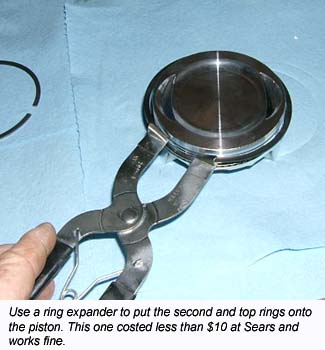
- A piston ring expander, for installing the rings onto the piston. A cheap but effective one is available at Sears (not needed if you purchased the pre-assembled option from us)
- Some way of supporting the back of the bike such that the back wheel is off the ground. A jack type bike lift or swingarm stand works great for this. You can improvise with a milk crate if you get
someone to help you lift the bike onto it. But you'll need the back wheel off the ground and the ability to turn it.
- Some .065" diameter (or thereabouts) solder to be used when checking squish clearance.
- A .001" reading dial or vernier caliper for checking pushrod lengths.
 |
 |
- Disassemble the top end. This will vary somewhat from bike to bike. Consult your service manual, it's your best source of information. Here are a few tips though that may not be in your service manual:
- Remove the spark plugs before attempting to rotate the engine.
- Rotate the engine using the back wheel, with the transmission in top gear
- Be sure the engine is rotated to the valve closed position before attempting to loosen a rocker box. This will remove the valve spring pressure from the rocker box and prevent possible damage. To make sure
the valves are fully closed, rotate the motor forward while watching the intake rocker. When you see the intake valve open, and then close, the next occurrence of TDC on that cylinder is a good place to stop.
Check piston position using a tie-wrap, straw, or similar soft object held through the spark plug hole.
- When it comes time to remove the pistons, first place rags under the pistons to eliminate the possibility that your wrist pin circlips might fall into the crankcase.
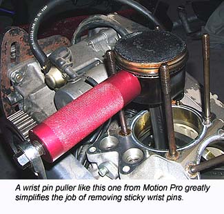
- You'll probably find that the wrist pin does not want to slide out easily. The best solution for this is to use a wrist pin puller, but if you don't have one, the pin can be carefully tapped
out using a small hammer and a punch. It's very important that your tapping does not get transmitted through the connecting rod! Doing so can damage the rod and/or the big end bearing. Have one
person support the piston while another person taps very lightly from the opposite side. Be patient, don't hit it hard.
- Gap your rings. The rings we provide in our engine kits are file-to-fit, meaning you must set your ring gaps before installation. Note that we offer the option of performing this service for you when you purchase
one of our engine kits:

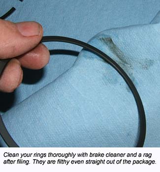
- Clean your pistons and rings thoroughly using the brake cleaner. They are filthy as they come out of the packages (even if they don't look it) and you need them to be spotless.
- Clean your new cylinders thoroughly using soap and hot water. Dry them completely.
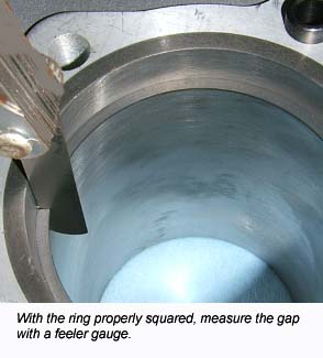
- Start with the oil rails. Reference the instructions, but the oil rail gap typically has a very wide tolerance, anywhere from say .015" to .050" is a common spec. Square the oil ring
in the cylinder at least 1/2" down from the top. Resist the temptation to do this right at the top of the cylinder to simplify squaring the ring, you must check all rings at least 1/2" down the bore
for accuracy. Do not check ring gaps in the spigot end of the cylinder, it is notorious for distortion due to the lack of material backing it up. Check ring gaps from the top of the cylinder only.
It takes very little variation in bore size to cause a large variation in ring gap so using a place that's round even in an unstressed cylinder is critical. Ideally you'd even clamp the cylinder
in a torque plate to simulate the stresses of an assembled engine, but 1/2" to 1" down from the top on an unstressed cylinder is a good place.
- In the unlikely event that the oil rail gap is too small, you probably won't have much success filing it wider. Instead, just touch one end of the rail to a grinder. Then deburr it well using a file,
you do not want any burrs on the rings.
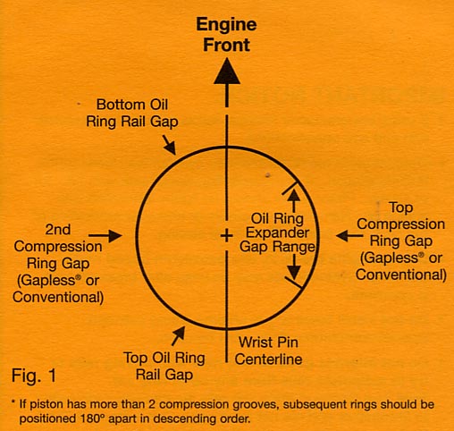
- Once the oil rails are ready, assemble the expander and oil rails on the piston, orienting the gaps per the instructions. Take great care to avoid overlapping the ends of the expander, they must
butt up to each other. Double and triple check this.
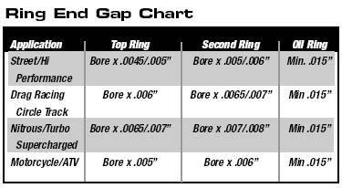
- Identify the second ring. It will most likely have a marking to indicate which side goes up. The instructions that come with the rings will have this information, as well as suggested ring gaps
for various applications (gasoline, nitrous, nitro, etc) and bore sizes. If you're not sure on the ring gap, call us to consult. Place this ring in the bore near the
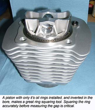
top of the cylinder. Put the piston into the cylinder upside down, and push the second ring down the bore. The piston will stop at it's oil ring. An inverted piston with oil rings installed like this
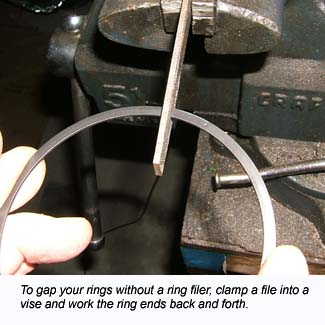
makes an excellent ring squaring tool. Measure the gap using the feeler gauges. To adjust the gap, clamp your file into a vise and squeeze the two ends of the ring against the file while moving it
back and forth. Be careful, don't overshoot your desired ring gap! Keep the two ends of the ring parallel and square to each other as well, don't allow them to file into a "V" shape or lean to one
side or the other. When you've achieved your final gap, very carefully deburr all four edges of both ends of the ring, using your file. This step is critical! Rings must be able to move freely in
the ring groove, any burrs will inhibit that movement. Clean the ring thoroughly after all filing operations are done. Don't put it on the piston yet, you'll need the piston with just the oil
ring to use as a squaring tool for the top ring.
- Repeat the above for the top ring.
- Install the second and then top rings onto the piston using the ring expander. Be very careful not to scratch the piston along the way. Make sure the rings move freely even when the ends are tucked into the groove.
Orient all gaps per the instructions. Double check that the top and second rings have their dot markings up. Triple check this, it's not a mistake you want to make.
- Repeat the above steps for the other piston and it's rings.
- Preassemble your pistons into the cylinders. Again, this is offered as an optional service, together with ring gapping, when you buy an engine kit from us:
- Put one of the wrist pin circlips into it's groove in the wrist pin hole. Make sure it's fully seated in it's groove.
- Clean the anti corrosion coating off the wrist pin using some brake cleaner, lubricate it with assembly lube, and insert it into the wrist pin hole.
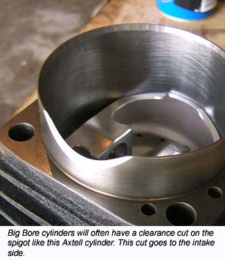
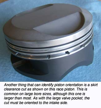
- Identify the cylinder to be installed as either a front or rear. In most of our kits, the cylinders are identical and can be installed in either position. However, on larger bores in particular,
the cylinder may have a clearance cut on it's spigot that needs to be oriented to the intake side.
- Turn the cylinder upside down and on a soft rag to avoid scratching the head gasket surface.
- Smear liberal amounts of assembly lube onto the rings and the piston skirts. Try to avoid getting lube onto the piston above the top ring.
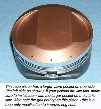
- Place the piston top into the spigot and let it rest on the top ring. With most of our kits, the piston can be installed either way. However, if you have one valve pocket that's larger than the other,
that valve pocket needs to be positioned to the intake side. Likewise, if there is any kind of a clearance cut on the piston skirt, that side needs to be
positioned to the intake side.
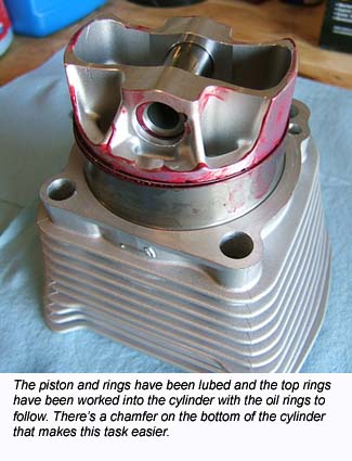
- Carefully work the top ring into the spigot using your fingernails. If you need more pressure, use a piece of hard plastic, never use anything made of metal. The blunt end of a Bic pen works well.
Do the same for the second ring and finally the oil ring
- Push the piston into the cylinder. It should have normal resistance from the friction of the rings against the cylinder wall. If it take excessive force, pull it back out and investigate the possibility
that an oil ring came out of it's groove and got sandwiched between the piston and cylinder wall. It's rare, but it can happen. Another possibility when the piston does not want to push down
is air trapped between the piston and the rag under the cylinder. You can put the cylinder dowels in place to avoid this.
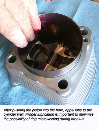
- Apply assembly lube to the cylinder wall liberally.
- Turn the cylinder right side up and push the piston down the bore. Using a clean shop towel, wipe any assembly lube off of the cylinder wall. The cylinder wall below the piston is lubed well but above the
piston should be free of any lube
- Repeat the above steps for the other cylinder.
- Install the cylinders and pistons:
- Thoroughly clean the base gasket surface on your engine cases. Try to avoid scratching it.
- Place your new base gasket over the cylinder studs and slide it down to the crankcase. Make sure it's oriented correctly such that the alignment dowel goes through the appropriate hole in the gasket
and the oil drain hole in the gasket is situated over the oil drain hole in the crankcase.
- Rotate the engine so that the connecting rod is about halfway up.
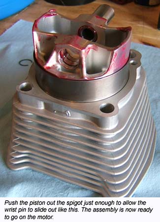
- Carefully push the piston down such that wrist pin hole clears the spigot. Do not push it farther or the oil ring will be at risk of popping out of the spigot. Put your fingers over the edge of the spigot to make sure this
doesn't happen.
- If your engine kit came pre-assembled, two of the circlips are already installed in the pistons. This is to make it easier for you.
- Position the wrist pin part way into the piston such that the area between the wrist pin bosses is clear.
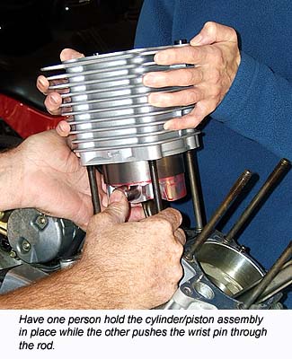
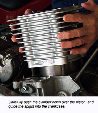
- Carefully place the cylinder and piston assembly over the cylinder studs and slide it down. Have one person hold the cylinder while the other person puts the top end of the connecting
rod into position and slides the wrist pin through.
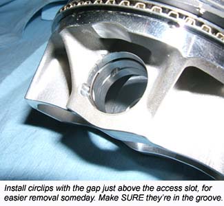
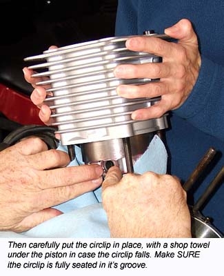
- With a clean shop towel under the piston to keep a dropped clip from falling into the crankcase, carefully install the remaining wrist pin circlip. Install the clip such that the gap is not directly lined up with the access slot in the piston; that access slot is there to make the clip
easier to remove some day. 45-90 degrees away from the access slot is a good place to be.
- Be absolutely sure the clip is fully seated in it's groove! That is not a mistake you want to make. Double check this. Triple check this. When
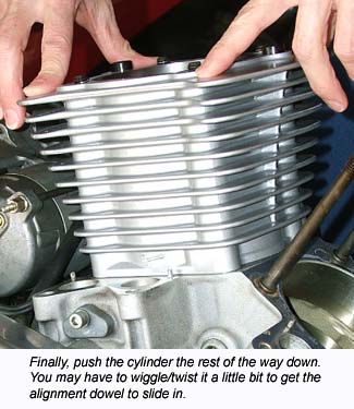
you'd be willing to bet your life that both clips are fully in place, carefully squeeze the piston up into the cylinder and then push the cylinder down over the piston and onto the crankcase as shown in the pictures below.
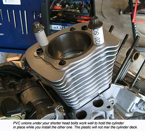
- For holding the cylinder down while you turn the motor to position it for the installation of the other cylinder, some 1/2" PVC unions and your shorter head bolts work well. The PVC will not damage
the cylinder deck surface.
- Repeat the above steps for the other cylinder.
- Check the squish clearance:
- This step is not described in your factory service manual, because stock motors are spec'ed such that the squish clearance is safe even
in a worst-case tolerance stack-up situation. This means that the majority of stock engines have excessive squish clearance.
- In the interest of maximizing power and efficiency while minimizing detonation, we supply thin gaskets with most kits to help optimize the squish clearance.
- This leaves open a small possibility that your squish clearance could come out too tight, causing piston to head contact.
Although the chances of this are very slight, leaving things to chance is no way to put together a motor, and checking the squish clearance
is fast and simple to do.
- Instructions for checking and adjusting the squish clearance can be found here.
Follow that link and give it a read to make sure you get the most out of your build and avoid any possibility of a problem here.
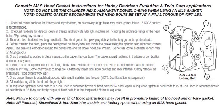
- Install the heads:
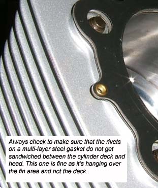
- Place the head gasket onto the cylinder. If you're using a multi-layer steel gasket that's held together with rivets, look carefully at the position of the rivets. Any rivet that may
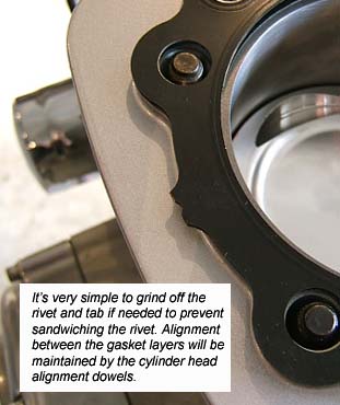
get sandwiched between the head and cylinder will need to be removed. They're very easy to remove using a bench grinder, simply grind away the entire tab that contains the rivet and deburr.
- Also note that multi-layer steel gaskets do not use o-rings around the alignment dowels the way the factory gaskets do. If you install o-rings on the dowels with a multi-layer steel
gasket, you guarantee yourself a leak.
- Very carefully place the head over onto the cylinder and gasket, taking care not to scratch the deck.
- Lube the threads, shanks, and undersides of the heads on the head bolts and install finger tight. Torque in the order shown in your service manual. For multi-layer steel gaskets,
torque all head bolts to 9ft-lbs, then 14, 22, 35, and finally 42ft-lbs. For composition type gaskets, follow the procedure described in the manual.
- Clearance the rocker boxes:
- This step is not described in your factory service manual simply because with all stock components, there's plenty of clearance. But it's incredibly important on a performance build.
It's not optional! Unfortunately, it's also one of the hardest steps to get people to pay attention to, and believe it or not, we have more trouble with professional mechanics
skipping this step (or taking it lightly) than with the backyard tinkerers, because the pros tend to think they already know how to put on a rocker box. Take this seriously please!
- The most critical clearance in the rocker box is the clearance between the valve springs and all areas of the rocker box around it. If the valve spring or retainer is allowed to touch the
rocker box, it forces the valve to land sideways on the seat. This causes seat recession and the resultant loss of seal, which of course saps power among other things. Performance springs
are larger in diameter than the factory springs and they will generally want to touch the rocker box. You absolutely must provide a minimum of .025" of clearance all around the valve spring
and retainer. Grind or file on the rocker box as needed to achieve this clearance. Note that with a beehive spring pack, this probably won't be an issue, but check it anyway. With
a conventional straight wound performance spring pack, it will almost certainly be an issue.
- The other rocker box clearance to look at is the clearance between the rocker arm and the underside of the rocker box cover. With high lift cams, the rocker arm will often make contact
with the rocker box top, which not only causes noise, but can cause leaks as well. Use a little play-dough or modeling clay to check this clearance.
- Check the pushrod lengths:
- Again, this step is not described in your factory service manual simply because with all stock components, the stock pushrod lengths are correct.
But if your build has head work, or any other changes to the valve train, this is definitely a check you need to make.
- When we configure a package that includes head work and cams, we estimate the pushrod lengths you need with consideration for the head work
and cam base circles. More than 95% of the time, we hit it within an acceptable length range.
- However, there are a lot of dimensions involved, many of which are on components that are not in our possesion while preparing your package.
Each of those dimensions has a tolerance, and depending on how the tolerances stack-up, it's possible your pushrod lengths won't be correct
- Checking your pushrod lengths during assembly is dirt simple to do and only takes seconds. So there's no reason at all to leave this to chance.
Even on a motor build that uses stock heads and cams, it doesn't hurt anything to check it.
- The method we suggest for checking it is described here. Follow that link and give it a read, it may just save
you a big headache down the road.
- Finish the assembly. For the remainder of the assembly, you should follow the factory service manual. Here are a few tips that you may not find in it though:
- Place a little assembly lube on the valve stem tips and tops of the pushrods prior to installing the rocker boxes.
- It's very important to position the motor correctly before attempting to install a rocker box. Not only must the motor be at or near top dead center (TDC), but it must be at the correct TDC.
A four stroke engine makes two complete revolutions to complete it's cycle, and therefore the piston passes through TDC twice. One of those times is overlap TDC, which has the valves slightly
open. You do not want to remove or install the rocker box with the motor in this position. Turn the engine one complete revolution from overlap TDC to get to compression TDC. Both valves are
closed at compression TDC, so this is the position you want to install the rocker box. An easy way to tell if the motor is at TDC is to turn it forward while watching the intake lifter
or pushrod. You will see the lifter or pushrod go up and then down again. The next TDC that occurs after it goes down is compression TDC.
- Thoroughly oil the valve springs and rocker arms after you've torqued the rocker box down. Pour engine oil all over them, and also over the pushrod end of the rocker arm, allowing oil to flow
down the pushrod tube. It takes awhile for oil to get to the top end, and you do not want it running dry while the oil is making it's way up there.
- Do yourself a gigantic favor and replace the two lower intake manifold bolts with hex head bolts, so that you can easily get to them with a standard wrench. The size you want is 5/16-18 x 3/4.
- After assembly, but before touching the starter button or installing spark plugs, turn the motor over using the rear wheel through two full revolutions of the crankshaft to check for any mechanical
interference of components. The starter is very unforgiving and it will damage parts if something is amiss. If you feel any mechanical interference, disassemble to investigate the root cause.
- SPARK PLUGS: It's VERY important that you run the correct spark plugs with your new HAMMER PERFORMANCE engine kit, or unwarrantied engine damage will result.
For all of our engine kits, we specify the HD 10R12X Gold plugs that were stock in XR1200 models, available here or at your dealer under part number 27794-08.
- SPARK PLUG GAP: Normally aspirated, pump gas motors with the stock coil typically work fine with the stock .038-.043" gap. In the unlikely event you experience misfiring
under high load, run the gap tighter and see if it helps. If running the gap tighter stops the misfiring, consider
a higher voltage coil so that you can go back to the .038-.043" gap.
Boosted (turbo or supercharger) and fuel (nitro or nitrous) applications almost always require tight gaps, even when used with hot coils and CDI ignitions or magnetos. A gap in the .020-.025" range
is common in these applications.
- SPARK PLUG WASHERS: 30 degree full dome pistons can sometimes try to hit the spark plugs. This may happen with the engine cold, or it may clear when cold and instead close up the plug gap after the motor is run for
a bit. If you have 30 degree full dome pistons, it's important to check for this, and adjust the spark plug position for clearance using indexing washers. Complete engine packages that come with
these pistons all include a package of indexing washers. If you have 30 degree full dome pistons and don't have a set of indexing washers, contact us and get a set before starting your motor.
To determine the number and thicknesses of the washers needed, bring a piston to TDC and screw in a plug by finger until it touches the piston (ALWAYS use high temp anti-seize on spark plug threads!).
Adjust the depth with the washers until you have at least .040" of clearance. If the gap closes up when the engine gets hot, add another washer.
- OIL: For break-in purposes, any low cost grade of 20W-50 oil will be fine. We actually use the Wal-Mart branded stuff that comes in gallon containers. After break-in (see below), change your oil and
use your favorite brand of high quality 20W-50 motor oil, preferably something formulated for air-cooled V-Twins.
- Tune Your Kit Properly. It is absolutely imperative that your motor have appropriate ignition timing and fueling for it's new engine kit, else the kit will be damaged in short order. You need to put a safe tune into
it initially, and then after break-in you can fine tune it for maximum performance. Please be aware that we cannot warranty kits damaged by improper tuning, so take this seriously please!
If you're farming out your installation, please make SURE the installer gets a copy of these tuning instructions and follows them. Shop installs account for less than 10% of our sales but also account for
more than 90% of the cases of scuffed pistons. This is because all too often, they don't get a copy of the tuning instructions, or in some cases they get them but they ignore them.
Scuffed pistons are usually the result when that happens. If you have any doubt that our instructions were followed correctly, please take personal responsibility for the tuning process and
make sure it's done per our instructions.
Ignition Timing
- The stock timing on all HD models is too aggressive for the increased compression that typically comes with a performance engine kit. Higher compression speeds the
burn and timing advance must be reduced from the factory level when installing an engine kit. Incorrect setting of the ignition timing is the number one cause of scuffed pistons.
- One of the biggest tuning mistakes we run into is people who run their ignition timing up (i.e. more advanced), mistakenly believing this enhances power. Nothing could be
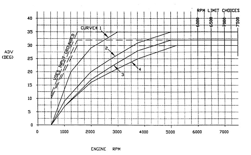
further from the truth! We have dyno tuned thousands of bikes, and the typical street hot rod Harley with 10:1 or 10.5:1 compression makes maximum power at about 28-30 degrees
total advance. Furthermore, they like the timing brought in slowly - not all in until 4500-5000rpm. This is the curve you need to achieve. More timing than this makes the motor
run hotter, lose power, and puts the engine kit at risk of scuffing or other damage, so please pay particular attention to this!
- Furthermore, if your motor is dual plugged, you need to retard the timing an additional 5-7 degrees across the board from the above setting.
Dual plugs cause a faster burn and retarding the timing like this is necessary to prevent detonation damage and piston scuffing.
If you're unsure how to retard the timing an additional 5-7 degrees, contact us and let us know what ignition you're using, we're happy to help.
- Never, ever, ever attempt to adjust the timing by listening for ping, many motors have been destroyed by using this method, and max power typically occurs well below
the threshold of ping.
- If your bike is injected, please contact us for a timing map that will be safe for your build. You will need an appropriate flash tuner device (see the fueling instructions below,
but we recommend, offer, and support the Dynojet Power Vision).
- If your bike is carbureted and has a crank trigger (04-up XL's and all Twin Cams), you have no mechanical timing adjustments available to you, and you must replace your
ignition module. If using a TC88A, set it on initial 2, slope 0. If you're using a Dyna 2000 TC-3 (DSPT), set it on curve 28C.
- If your bike has a timing plate or nose cone module, you have the option of either backing down the timing or replacing the ignition with a module that will give the proper curve (preferred).
- If you're using the factory ignition module, start with the timing set to the factory correct position per the service manual procedures. Then put a mark on the timing plate (or nose cone
module) that extends onto the inside of the nose cone. Rotate the plate or module counter clockwise .090" as measured at the perimeter of the plate. If you have a marked timing plate, this will be one
and a half hash marks.
- If you're using a Dyna 2000 or 2000i, static time the module using the LED as described in the module's instructions, and put the module on Curve 4.
Watch this video to see how to static time and set the module.
- If you're using an Ultima module, your ignition does not have a suitable curve for our engine kits. Many people assume the Ultima is the same as a Dyna 2000i, because the DIP switches
are the same, but the Ultima's curves are actually very different and much more aggressive than the Dyna's curves, which puts the pistons at risk.
The only way to achieve a proper curve with the Ultima module is to get the programming kit and construct a curve like the Dyna 2000i's curve 4.
- If you're using a DTT 1005 ignition, static time the module using the LED as described in the module's instructions, and put the module on Race Curve 0.
- If you're using a DTT 1005S-EX ignition, static time the module using the LED as described in the module's instructions, then rotate it clockwise .030" as measured at the perimeter of the plate,
and set it on curve 0.
- If you have a Crane HI-4 module (nose cone with potentiometers), please don't use it with our kits. Practically every customer who uses that module with our kits ends up damaging the kit. We suggest the Dyna 2000i instead, static timed and set on curve 4 as described above.
- If you're using any other ignition, please check the curves as described in the ignition instructions and choose one that meets the requirement of a soft curve, not all in until 4500-5000rpm, and
not exceeding 30 degrees total advance. In other words, as similar as possible to the Dyna 2000's curve 4. If you need help with this, contact us and please provide a copy of the instructions, we'll help you figure it out.
Fueling
- Although nobody can jet your bike with any precision via internet, you have to start somewhere, at a safe level that will avoid engine damage. Below are our recommended starting points.
Just keep in mind that these are starting points only, and further adjustments will likely be beneficial.
- If using a stock CV40 on a 1250 or 1275, a good starting point is a 185 main and 45 pilot. Also access the
idle mixture screw (underneath a plug that's on the underside of the carb near the outlet) and set it to 3 turns out from lightly seated.
Please Note: If you're using a Forcewinder air cleaner on a CV carburetor, please contact us for information on a needed modification. Failure to make this modification will
make your motor run lean and possibly damage the engine kit!
- A Mikuni HSR42 on a 1250 or 1275 should start with a 165 main, 25 pilot, and a 97 needle on the middle position. For an HSR 45 use a 175 instead.
Then fine tune using the Mikuni HSR Tuning Manual as your guide.
- An S&S "E" or "G" on a 1250 or 1275 should start with a 68 main and a 29.5 pilot.
- If your bike is injected, you need an appropriate tuner device, one capable of flashing a new tune to your bike's ECM.
Do not, under any circumstances, start your bike after installing the engine kit before your new tune is in place!
Engine damage occurs very quickly when this mistake is made.
We do not recommend, offer, or support piggy-back type tuners for use with our kits (Power Commander, Cobra, Fuel Pak, Techlusion, Dynatek Fusion, etc).
A piggy-back tuner works by hanging outside the factory ECM and intercepting and modifying signals that come and go, essentially fooling the system.
This approach is workable for pipes and air cleaners, but when making changes in displacement it has limitations, and these limitations can make it dangerous to the health of your engine kit.
As such, damage to your engine kit from mistuning is much more likely when attempting to tune it with a piggy-back tuner.
The proper type of tuner to use with our kits is a flash type tuner, which instead lets you rewrite tables and other settings in the ECM to actually teach it about the configuration.
Among flash tuners, the Dynojet Power Vision (PV1, PV2, PV3) stands out for both it's tremendous capabilities and it's ease of use.
For this reason, the Power Vision PV1, PV2, and PV3 are the tuners we have chosen to recommend, offer, and support directly with a tune.
Most other flash type tuners can be used with our engine kits.
There is, however, one flash tuner on the market that is not suitable for use with our kits, and that's the emissions-legal SE Street tuner (the only one they sell anymore, for the last several years).
So do not attempt to use the SE Street tuner with our kits, engine damage will certainly result.
For any other flash type tuner, it will be up to you to implement the tune to our specifications.
It's extremely important that you get the spark advance tables in particular from us!
In many cases, our kits speed the burn significantly, and if the spark advance tables are not implemented correctly, the motor will run hot, make less power, and you could scuff your pistons.
So take this seriously please.
Contact us for table values and settings that need to be implemented in your tune.
Again, ALWAYS flash your new tune before starting the motor for the first time!
Engine damage can occur very quickly if you've installed one of our engine kits and start the motor before flashing the correct tune to the ECM!
This is a very expensive mistake to make.
Engine damage from mistuning is not covered by warranty because it does not represent a defect in the kit.
Also note that with a flash tuner, you must actually go through the process to flash the tune to the bike's ECM.
With some flash tuners (e.g. Power Vision), you can load the tune onto the tuner without actually flashing it to the ECM.
The tune is not yet implemented until you perform the flash operation, thus rewriting the tables and settings in the bike's ECM.
We have had customers make this mistake and promptly destroy their engine kit. Don't be that guy!
Special note on the FP3: The FP3 is really marginal for tuning our kits, and we discourage it's use. Not because we want to make money on selling you a tuner, hell, we don't care where you buy it, and we make next to nothing on the tuner anyway. But because we want you to be successful with the kit, and we know from experience that FP3 users are far, far more likely to damage their kits from mistuning than Power Vision users. It's not even close.
If a Power Vision user follows our instructions and gets his tune from us, he's fine, he won't hurt his kit.
FP3 users on the other hand have to punch a ton of values (which we will provide) into their phones to get their tune in place, because V&H's closed ecosystem doesn't provide a PC program to build tunes with, like every other tuner in the world does. They don't provide that program because instead they want all tunes to be routed through them, so that they have a copy and have a record of what tune is in everyone's bike. It's the new way of doing business in the tech world, control everyone and invade their privacy. But anyway, that process of punching values into your phone is error prone, which we believe is the reason FP3 users damage their kits too often. We don't really know, though, because they have no way to send us a copy of the tune to examine. The whole thing is just a major PITA for us and we wish it had never been brought to market. Don't expect anything in the way of support beyond providing you with table values and settings. Get your tune direct from V&H at your own risk, we've had customers do that and promptly damage their motors. Again, this is not covered by warranty because it does not represent a defect in the kit.
If you're using a Dynojet Power Vision PV1 or PV2 we will provide you with a starting point tune.
Please contact us before you even start your motor.
We very much prefer to modify your stock tune as opposed to basing your new tune on a canned map.
The reason is that there are numerous parameters in the tune that we don't want touched, and canned maps often have changes in those areas.
As a result, sending out tunes based on canned maps creates support headaches, as it introduces problems that are difficult to troubleshoot.
So to avoid those issues and ensure the process goes smoothly, email a copy of your original tune to us.
To retrieve the original tune using your Power Vision PV1 or PV2, go to Program Vehicle [accept], Load Tune, Load Copy, Load Copy of Original.
It will let you put a copy of the original tune into one of the slots.
Then pull that tune over to the PC using the USB cable and WinPV, save it as a .pvt file, and email it.
We'll make the needed changes and send it back to you with further instructions.
If the above instructions for retrieving the original tune are not clear to you, please watch this video.
Do not send us the .stk file that the WinPV software creates as a backup of your original tune, this does nothing for us.
Please retrieve the original tune and save as a .pvt as described above.
If your factory original tune has been lost due to being previously overwritten, follow the process and send it anyway.
Even if it's not original, we can usually glean some useful information from it.
If the tune is not original and the bike's VIN has been deleted from the tune, we will also need your bike's VIN.
But it's best to send the original tune if it's available, because generating a new tune based on the VIN is a multi-day process.
If you're using a Dynojet Power Vision PV3, again, we will provide you with a starting point tune.
But the procedure is a little different as compared to the PV1 & PV2.
Download our Step-by-Step guide for tuning with the PV3 for all the details.
Regardless of which flash tuner you use, put at least 20 miles on the new engine before doing any log tuning process (Power Vision Auto Tune, SEPST SmartTune, TTS Vtune, etc).
While log tuning, continue to follow the break-in instructions below. Do not go for any of the high load or high rpm cells!
Just take what it gives you.
Repeat as needed, building on the previous result each time, to dial in your displacement and VE tables.
Once break-in is complete, you can go for whatever cells you can hit.
-
Our engine kits require premium fuel.
Fuel is rated differently in different parts of the world, and the various packages we put together for customers have different compression, and higher elevations also require less octane than lower elevations all else equal.
But generally speaking, fuel with a minimum octane of 92 (R+M)/2 or 97 RON should be used.
The (R+M)/2 rating system is used in the US, and RON is used in most of the rest of the world.
- Proper break-in is critical to realizing maximum life and performance of your engine kit! We can't stress this enough. Follow these steps to the letter. Ignore any alternative methods you may read about
on the internet!
- Minimizing heat is absolutely essential to successful break-in, and excessive heat will damage your pistons and forever condemn your motor to be a mediocre performer. The reason for this is that
neither your rings nor your cylinder bores are perfectly round on initial assembly. Therefore, the rings are actually only making contact with the cylinder walls in a few places. The tension of
the rings is concentrated in these places, increasing friction and heat. This condition exists until the rings have a chance to carve the cylinders into their shape. While that process is taking place,
however, the rings and the pistons are very vulnerable to damage from excess heat. You can learn more about this phenomena by researching "ring microwelding". It's a very real risk to your engine!
- The assembly lube you put on the rings and pistons is to help combat ring microwelding. Yes, we know that some shops recommend minimal or even no lube at all to better assist the break-in
process. We don't subscribe to that theory. Your rings are at much greater risk of microwelding than they are of failing to seat. They will seat just fine. You need to pay attention to the possibility
of damaging them.
- On your initial start-up, run the engine no longer than 10 seconds. Use a clock with a second hand or a stop watch. Don't guess! Shut it off and allow it to cool completely to room temperature.
A little bit of patience now will go a long way to providing you with a strong motor that lasts a long time.
- For your second heat cycle, run the motor no longer than 20 seconds. Again, time it properly, don't guess. Allow it to cool completely.
- Repeat these heat and cool cycles with run times of 30 and 40 seconds.
- You're now ready for your first ride. Keep the rpm's down as much as possible and keep air flowing across the cylinders. Ride it no more than a mile, shut it down, and let it cool completely
- For your second ride, treat it similarly gently. Keep your rpm's below 3500 and keep air moving across the cylinders. Ride it a couple miles and let it cool completely.
- For the next 50 miles, do not exceed 3500rpm and avoid using full throttle. Vary your speeds, allowing the engine to pull and then decelerate gradually. This reversal on the rings, from pressure to
vacuum, assists in the seating process.
- For the next 500 miles, stay below 4000rpm, avoid using full throttle, and keep the heat down.
- Once you're past the 500 mile break-in period, change your oil. During break-in, the rings have carved the cylinders into their shape and the shavings have been captured in the
oil, so you want to change the oil to get that stuff out. Use any high quality 20W-50 oil formulated for air-cooled V-Twin engines.
- The vast majority of our customers do not get their bikes dyno tuned. Most just follow our tuning instructions, achieve a perfectly fine tune, and live happily ever after. And
truth be told, it can be somewhat risky to have your bike dyno tuned, because we often see dyno tuners disregard our instructions and load up spark advance tables, or run the spark advance too
aggressive, and this can cause the engine kit to be damaged a couple hundred miles down the road, if not sooner. So if you do choose to have your bike dyno tuned after installing our kits, make sure the guy doing the tuning understands the dangers of varying from our instructions on the spark advance curves or tables. Honestly, it's best to instruct him not to change the spark advance at all, from our instructions.
Also, if your bike is injected and you're using a Power Vision, consider the Target Tune add-on instead of a dyno tune. The Target Tune kit adds wide band auto tune capability to your Power Vision, as found in a dyno tuning environment. But it also adds closed-loop wide band operation which constantly adjusts your fueling as you ride. No dyno can do that, so in that respect it's better than a dyno tune. The cost is competitive with a typical EFI dyno tune session, and you'll be in control of the tune, not risking your motor to the skills of a dyno tuner (or lack thereof) and also be able to retune by yourself for any air flow changes you make in the future..
- Frequently Asked Questions
-
Where are my circlips? Help!
- If you bought the optional preassembly service, we've packed two of the circlips in a little plastic baggy with one of the wrist pins. The other two are already
installed in the pistons for you, to make it easier.
-
You sent me a new main jet but it doesn't fit my carburetor, did you send me the wrong one?
- Every single time we've had this
question, it's been because the carb has a kit in it and the emulsion tube has been replaced with an aftermarket piece that
uses different jets. We recommend that you go back to the stock emulsion tube and lose the jet kit. However, if you'd like to keep using it, you'll have to get jets
from the company who made it. We're happy to take back the jet you purchased from us, no worries there.
-
Do I need to clearance the rocker box as shown in the instructions?
- If your heads are completely stock, ignore that whole step. If your heads have been prepared, but have beehive springs (smaller on the top, and more than 90% of what
we're shipping anymore), you don't need to clearance around the spring, however, you may still need to provide clearance for the rocker arms as shown, to prevent them from
hitting the underside of the cover. You only need to clearance around the springs if you've got big diameter heavy duty springs as shown in the pictures above.
-
Why doesn't the Grindlock tool fit my pinion gear? Did you send me the wrong one?
- This is covered in
the cam installation instructions since the tool is generally used in conjunction with a cam installation, but it's a common
enough confusion that we're going to cover it here too. The basic issue is that
you're trying to install it as if it's another gear, that just meshes with the pinion gear like it's any other gear. It'll never go on that way. But if you
install it by pushing it over the end of the pinion gear instead, it falls right on. See
the specific instructions here if this still isn't clear to you.
-
Why can't I get my exhaust flanges back on?
- Starting in 2002, HD went to a new, thicker exhaust flange, that they still use today. This thicker piece gives less clearance to the top cooling fin
on the cylinder, and it doesn't take much head decking to reach the point where the fin interferes with your ability to put the flange on.
This is especially likely with the late model large fin style cylinders. The fix is to simply grind a little off the bottom of the flanges.
-
My cylinder won't push all the way down against the case, why is that?
- When trying to put 1986-2003 style small fin XL cylinders onto a 2004+ XL motor, the lowest fin will hit the tappet cover base. This is one of the big reasons
we recommend using big fin cylinders only on 2004+ XL's. The other reasons are that big fin cylinders cool better and properly match the 2004+ heads. So the best solution
if you're in this situation is to contact us and arrange to exchange your kit for a big fin version. However, if you really want to run the small fin cylinders, you'll need to grind off the
lowest fin to gain the clearance you need.
- If the above is not the reason, it's possible that the pushrod cover bases are interfering with the ability of the cylinder to sit all the way down. Loosen the screws that hold the
base on and move the base outboard within the clearance of the bolts to their holes and try it again.
-
Why do I have parts left over from my gasket set?
- The gasket sets are designed to cover a wide range of years and models, and not all the pieces are used on any particular bike. So long as you replaced all
the gaskets and seals and o-rings you encountered during the build, you're good.
-
What spark plugs should I use?
- The spark plug we specify for all of our engine kits is the HD 10R12X Gold that was stock in XR1200 models.
They are available here, or at your dealer under part number 27794-08.
-
My Mikuni carburetor touches the cylinder fins, what should I do?
- Although the Mikuni carb is a bolt-on, sometimes it will run into the cylinder fins slightly and this may prevent it from properly seating squarely in
the manifold. The fix is to simply do some very slight grinding or filing on the fins at the contact point. It shouldn't take much.
-
The screws for my air cleaner won't tighten up to my Mikuni carb, what should I do?
- Mikuni's use a little slip-on adapter to present a CV type bolt pattern for the air cleaner, and the screw holes are blind and not particularly deep.
As a result, sometimes it's necessary to shorten the air cleaner mounting screws slightly when using a Mikuni carb. Also, anytime you mount up a Mikuni
and use that slip on air cleaner adapter, check to be sure that the throttle stop linkage on the left side (rearward on the bike) does not hang up on
the air cleaner adapter. We've seen this on a handful of Mikuni's and it's potentially dangerous. Grind a small notch in the air cleaner adapter if necessary
to provide clearance.
-
Why won't my throttle cables adjust properly with the Mikuni?
- The bracket that holds the throttle cable guides on a Mikuni is designed for Big Twin cables. However, it's very easy to bend the bracket a little
and make it work with XL cables instead.
-
My engine kit is not marked front or rear. Does it matter which way it goes?
- See the pictures above that describe piston orientation, as well as the section above that describes how to tell a front cylinder from a rear. Most pistons have equal size valve
pockets and no clearance cut on the skirt, and therefore can be installed either way. But if you have either non-equal sized valve pockets or a clearance cut on the skirt, be sure to orient them correctly as described.
Likewise, most cylinders can be installed in either position. However, if there's a clearance cut on the spigot as shown above, that clearance cut needs to be oriented to the intake side.
-
What grade fuel should I use?
- Our engine kits require premium fuel. Fuel is rated differently in different parts of the world, and the various packages we put together for customers have different compression, and higher elevations also
require less octane than lower elevations all else equal. But generally speaking, fuel with a minimumn octane of 92 (R+M)/2 or 97 RON should be used. The (R+M)/2 rating system is used in the US, and RON is used in
most of the rest of the world.
-
If I torque down my heads as part of checking my squish clearance, do I need new gaskets?
- No. The MLS head gaskets and SLS base gaskets that we provide with our kits are in no way compromised by a torquing cycle, the way composition gaskets are. In fact, we reuse them on our
own bikes even after running the motor hard. We basically reuse them until the rubber coating starts wearing off. A simple torquing cycle doesn't hurt them a bit.
- Common Mistakes:
The vast majority of our customers install their kits with no problems. However, occasionally a customer get tripped up, here are some common mistakes:
- Removing your old wrist pins: Sometimes people try to tap the wrist pin out without properly supporting the rod, which transmits the impact through the big end bearing. This can cause a big end bearing
failure within a few thousand miles of installing the kit. Either properly support the rod, or contact us to get a wrist pin removal tool. It's much, much easier and cheaper to avoid this problem than to fix it later.
- Inserting your pushrod tubes: Sometimes people try to put the o-rings onto the tops of the tubes instead of directly into the pockets on the underside of the heads. This doesn't work. Always put the o-rings into
their pockets on the underside of the heads. Then insert the tubes up through them, making sure the o-rings stay in place.
- Torquing your head bolts: Despite the instructions above, some people follow the factory procedure. The head gaskets provided in our engine kits require the alternate procedure described above.
Using the factory torque procedure with the gaskets we supply may very well cause your cylinder studs to pull out of the case.
- Removing your rocker boxes: There are two common mistakes on this one:
- You should ALWAYS remove your rocker boxes before you remove the cam box cover. If you remove the cam box cover first,
the valve spring pressure will be applied to the cams with the cams only supported on one side. This puts your inner cam bushings and even your right case half at risk - we've literally seen the right side case half fracture
from doing this. Always remove the rocker boxes first!
- ALWAYS properly position the motor before removing a rocker box. Although it's more critical when putting the rocker box back on (see below), you still want the motor at or near compression TDC,
not overlap TDC! And you can't tell which TDC you're at by just looking at the static position of the valvetrain, you must look at the motion of the valvetrain as you rotate the motor forward to differentiate compression
TDC and overlap TDC. Rotate the motor forward and watch what's happening on the intake side. When you see the rocker turn and open the intake valve, and then close the valve, you're on the compression stroke. Proceed from there
to the upcoming TDC - use a straw through the spark plug hole to gauge piston position. It doesn't have to be exact. Compression TDC is about halfway between the points where the intake valve closes and the exhaust valve opens, so
it makes a good reference point. But if the piston is a little to one side or the other, it won't matter. Once you're at compression TDC, remove the rocker box. Now before you go removing the other rocker box, reposition
the motor to put that cylinder at TDC.
- Installing your pushrods: Your pushrods are different lengths on the exhaust vs. the intake. The longer pushrods go on the exhaust side. Make sure you don't mix these up. Also, it's a good
idea to verify your pushrod length is correct during installation, using
method #2 as described here.
- Installing your rocker boxes: There are four common mistakes on this one:
- ALWAYS make sure your cam cover is back in place before installing a rocker box. Just as described above for the removal process, you never want a situation where the valve spring pressure is applied
to the cams while the cam box cover is removed. Doing so creates great risk of a very expensive failure.
- ALWAYS properly position the motor before installing a rocker box. Just like the removal process, you need the motor positioned at compression TDC, and the process for differentiating compression TDC from overlap
TDC is similar. There's one big difference: during installation, you have to watch the motion of the pushrods instead of the rocker arms. The pushrods may not fall down by themselves while rotating the motor, too,
so put some downward pressure on them with your fingers while rotating the motor to accurately
observe their motion. Again, when the intake is moving down, you're on the compression stroke. Proceed from there to the
upcoming TDC as gauged with a straw through the spark plug hole. Do this individually for each cylinder, in other words, position the motor correctly, install that rocker box, wait for bleed down (see below),
position the motor correctly for the other cylinder, install that rocker box, and wait for bleed down before rotating the motor again.
- Before putting the rocker box in place, make sure you don't accidentally put the front rocker box on the rear and vice-versa. This is a mistake we see sometimes and it causes a lot of oil to come out the
breathers. There's a check valve in line with the breather passage and that check valve needs to be positioned to the middle of the "V". On a 91-03 XL, that check valve is an umbrella valve that sits in the middle
rocker box. On a 2004+ model, there is no middle rocker box, and the check valve is a plastic housing that sits on the floor of the rocker box.
- Do not rotate the motor until the lifters have had a chance to bleed down. When you tighten down the rocker box, the lifter plungers won't go down immediately, because it takes awhile for the oil to bleed
out of them. Therefore the valves open when you tighten down the rocker box. It generally takes 10 minutes or so for the lifter to bleed down. Give it 15 minutes to be safe. When you turn the motor over, don't use the
starter. Rotate it by hand using the back wheel. If you feel any mechanical interference, STOP, don't force it. Investigate the source of the issue. If you force it, or if you use the starter motor to turn the motor over,
you may bend parts.
- Adjusting your throttle cables: This is the number one power-robbing mistake we see people make! Entirely too many people just assume that when the grip stops turning, they're at full throttle.
But the throttle grip's stop is not the same as the throttle plate's stop!
If you want full power, you MUST make sure the throttle plate linkage, on the carb or throttle body, reaches it's stop BEFORE the grip reaches it's stop. To check this, hold the throttle grip wide open with one hand, then reach down
with the other hand and try to turn the bellcrank on the throttle body or carb farther in the open direction. If it can be turned farther before reaching it's stop, you're leaving free power on the table.
The proper cable adjustment procedure is to put slack into the idle cable, then adjust your pull cable making sure the throttle plate at the carb or throttle body is getting all the way to it's stop when the grip is twisted all the way,
then adjust your idle cable to take up the slack.
- Installing a clutch spring: Many kit installations involve the installation of a clutch spring. Be very careful that you place the spring onto the pressure plate, followed by the spring seat ring on top of
it, and then the retaining ring. People sometimes mistakenly put the spring seat ring under the spring instead of over it. The spring seat ring needs to be up next to the retaining ring, to keep in in place. Also
be very sure the retaining ring is all the way in it's groove before unwinding the spring compressor. People often fracture their clutch hubs because they try to release the spring without the retainer fully in place.
- Clutch Adjustment: ALWAYS put full slack into the cable, using the cable adjuster, before adjusting the clutch at the engine. ALWAYS keep an eye on the free play in the cable, and do a full clutch readjustment
of the cable and the adjuster screw on the motor if you see the free play going away. This issue is especially common early in a clutch's life, as the plates bed in. If you allow the free play to go away and you
don't readjust the clutch, the clutch will be destroyed quickly.
- Connecting fuel injectors: There are separate injector
connectors for front and rear, and they're labeled. Make sure you don't invert them. Many bad running issues have been traced to this mistake.
- Connecting head temp sensor: On some models, the head temp sensor connector is in close proximity to the rear oxygen sensor connector, and the connectors are identical. It's very easy to accidentally hook your head
temp sensor and rear oxygen sensor up to the incorrect connector. Be careful of this.
- Tuning: Despite the tuning instructions above, a small percentage of our customers do not properly reduce their ignition timing or increase their fuel delivery. This causes pistons to break, or more
commonly to scuff, because excessive heat causes them to swell up and run out of clearance. This issue is especially common with installations that are farmed out to a shop. All too often they either don't get a
copy of the instructions or they don't take them seriously because they're sure they already know how to do it. If you're having a shop install your kit, make sure they get a copy of these instructions and
understand the importance of proper tuning. If you have any doubt, take responsibility for the tuning process yourself. Have the shop contact us if they have any questions at all; we'd much rather answer questions than
deal with scuffed pistons later.
- More things to know:
- High lift cams require special clearancing procedures in the cam box and may require special tappets with longer anti-rotation pin flats for extra tappet pin clearance. Likewise, cams with high TDC lift figures (symptomatic of high amounts of overlap) will require piston to valve clearance checks. Refer to the appropriate Tech Tips article for more information, or call the shop with questions
- High lift and/or high overlap cams also require special clearance checks in the cylinder heads themselves. If we prepared your heads for you, and you told us what cams you're using, you're good
to go, we've set them up. But if your heads are not prepared for high lift and/or high overlap, you run the very real risk of problems like coil bind, valve to valve contact, or retainer to
guide seal contact.
- The above instructions are tailored for a person installing an engine kit at home, who may not have specialized tools like ring compressors, filers, and the like. As such, these instructions deviate somewhat
from procedures you may find elsewhere. We've found the techniques described above to be effective and safe, however.
|


